A4988 stepper motor driver
The A4988 is a microstepping driver for bipolar stepper motors.
It takes step/direction signals from a microcontroller and outputs controlled current to the motor coils, allowing:
✔ Full stepping
✔ Half stepping
✔ 1/4, 1/8, 1/16 microstepping
That means smoother motion, quieter operation, and finer positioning. It’s widely used in:
3D printers
CNC machines
Robotics
Camera sliders
And motion control projects!
✨ Key Features
✅ Drives bipolar stepper motors
✅ Adjustable current limit
✅ Microstepping (up to 1/16)
✅ On-board translator (no complex microstep tables)
✅ Reverse voltage and over-current protection
✅ Uses easy step/dir interface
✅ Small, breadboard-friendly module with potentiometer
📊 Electrical Specifications
Parameter Value
Operating voltage (motor) 8 V – 35 V
Logic voltage (VDD) 3.3 V – 5 V
Output current Up to ~2 A per coil (with cooling)
Step resolutions Full, 1/2, 1/4, 1/8, 1/16
Control interface STEP / DIR / ENABLE
Decay mode Slow / Mixed
Protection Over-temperature / Under-voltage / Over-current
Package DIP carrier / breakout module
📌 Note: The A4988 driver is usually sold as a breakout board with pins, mounting holes, and adjustment pot.
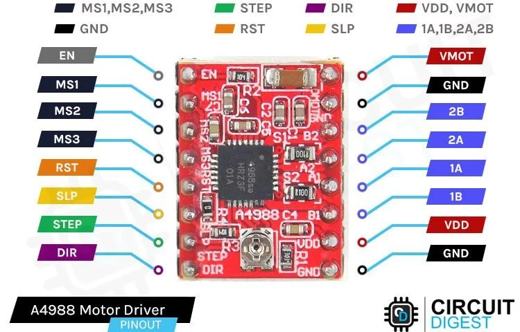
🔌 Pinout (Typical Breakout Board)
+-----------------------+
VMOT (1) (20) GND
GND (2) (19) RESET
STEP (3) (18) SLEEP
DIR (4) (17) MS3
EN (5) (16) MS2
MS1 (6) (15) MS1
GND (7) (14) RST/SLP*
5V (8) (13) STEP
SLEEP (9) (12) DIR
RESET (10) (11) ENABLE
+-----------------------+
* Some boards tie RESET and SLEEP together
Important Inputs:
Pin Meaning
VMOT Motor power (8–35 V)
GND Common ground
5V Logic power (from MCU)
STEP Step pulse input
DIR Direction control
ENABLE Enable/disable motor outputs
MS1/MS2/MS3 Microstepping mode selection
RESET / SLEEP Resets or puts driver to sleep
🌐 Microstepping Modes
You configure microsteps by setting MS1/MS2/MS3:
MS1 MS2 MS3 Mode
0 0 0 Full step
1 0 0 Half step
0 1 0 1/4 step
1 1 0 1/8 step
1 1 1 1/16 step
(1 = HIGH, 0 = LOW)
⚙️ How It Works (Simple Explanation)
VMOT (+ motor voltage) supplies power to the stepper coils.
STEP pin receives pulses — every pulse = one (micro)step.
DIR pin sets the direction of steps.
A4988 handles current regulation to each coil for smooth motion.
Unlike simple H-bridges, the A4988 uses chopper current control so your motor gets the right current even at high supply voltages.
🛠️ Typical Wiring With Arduino
Arduino A4988
-------- ---------
5V → 5V
GND → GND
Pin 2 → STEP
Pin 3 → DIR
Pin 4 → ENABLE (optional)
VMOT → 12–24V
GND → GND (power)
Motor A+ → Out1
Motor A– → Out2
Motor B+ → Out3
Motor B– → Out4
Don’t forget:
🔸 Connect grounds together
🔸 Add bulk capacitor (100 µF) near VMOT
🔸 Adjust current limit before running
🔧 Setting the Current Limit
There’s a little potentiometer on the board. You turn it to set the max current to your motor coils — so the driver doesn’t overheat or the motor doesn’t draw too much.
A simple estimate:
Vref = Current * 8 * Rs
Where Rs is the sense resistor on your module (usually ~0.05Ω).
Adjust Vref while measuring with a multimeter (watch datasheet for specifics).
⚡ Good Practice Tips
🧊 Heat Dissipation
If you’re near the current limit, add a heatsink or airflow — these chips get hot!
🧠 Noise Suppression
Some folks add a small 100 nF ceramic + larger electrolytic across VMOT/GND.
🕹 Use ENABLE
Pulling ENABLE LOW lets motor outputs drive; HIGH = disable (motor off).
🛠️ Common Uses
✔ 3D Printer axis control
✔ CNC machine stepper control
✔ Precision camera sliders
✔ Robotics joint/motor control
✔ Automated mechanisms
✔ Retro game and art installations
📌 Quick Summary
🎯 A4988 = stepper motor driver with microstepping
Easy STEP/DIR interface
Adjustable current
Smooth microstepping
Works with Arduino, ESP32, Raspberry Pi (with level shifting)
No specifications available.
0.0
Based on 0 reviews
No reviews yet. Be the first to review this product!
Login to write a review.